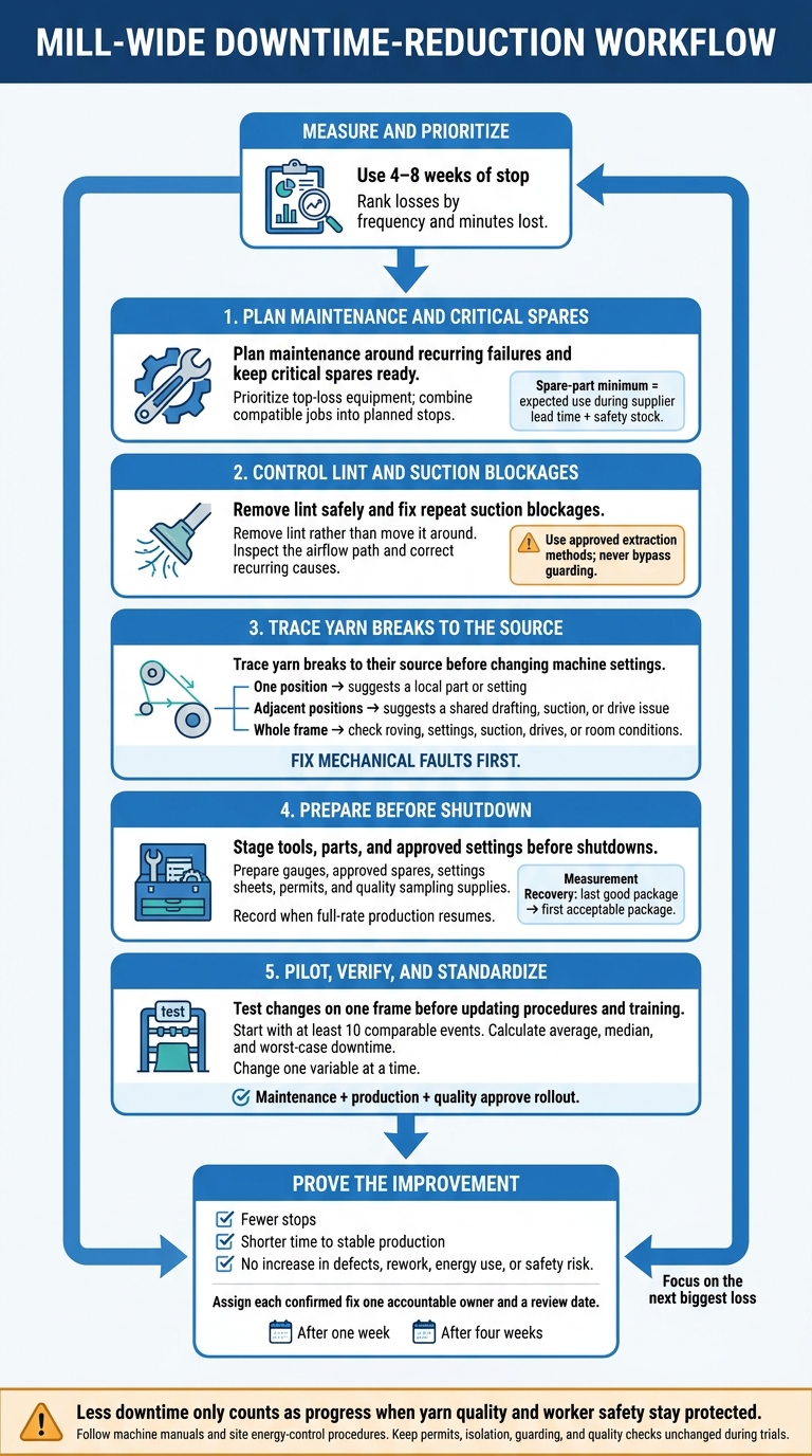
Reducing downtime in cotton spinning mills starts with measuring what stops production - and fixing the causes that cost the most time. Use 4–8 weeks of stop records to rank losses by frequency and minutes lost.
Then focus on five steps:
- Plan maintenance around recurring failures and keep critical spares ready.
- Remove lint safely and fix repeat suction blockages.
- Trace yarn breaks to their source before changing machine settings.
- Stage tools, parts, and approved settings before shutdowns.
- Test changes on one frame before updating procedures and training.
Track both stop frequency and time to stable production. Less downtime only counts as progress when yarn quality and worker safety stay protected.
How to Reduce Downtime in Cotton Spinning Mills
How to Minimize U/kg || Reduce Power Consumption per Kg in Spinning Mills || Sahoo Textile Academy
sbb-itb-0e617ca
Plan Preventive Maintenance for Critical Equipment
Use the top-loss list to plan preventive maintenance for frames that stop production most often. Combine jobs that share isolation, tools, or specialist labor into one planned stop, including yarn-count changes. Rank critical assets by downtime hours, failure frequency, MTBF, MTTR, safety risk, and lead time. Give priority to failures that stop an entire frame, affect yarn quality, or take a long time to repair.
Each work order should name the parts, isolation points, acceptance limits, and person responsible for return to service. Follow the machine manual for service limits, tolerances, lubricants, and procedures - not one calendar schedule for every machine.
Inspect Drafting, Spinning, and Control Components
Check top rollers, cots, aprons, bearings, and loading points for wear, glazing, contamination, looseness, uneven pressure, and damage. Inspect spindles, tapes or belts, rings, travelers, bearings, and drives for alignment, tension, wear, heat, and vibration. Record the machine and position number, condition, measurements, adjustments, replacement decisions, technician, and date.
Check stop motions, sensors, autolevelers, yarn clearers, and suction equipment for cleanliness, alignment, response, false stops, airflow restrictions, leaks, loose connections, and recurring alarms. Inspect filters, ducts, couplings, and belts, and follow approved calibration procedures. Only qualified, authorized personnel should work inside electrical panels.
Before servicing, notify affected employees and isolate every applicable energy source. Apply lockout/tagout, release or restrain stored energy, and verify zero energy. After the work, restore guards and interlocks and test them before restarting.
Assign Maintenance Tasks and Stock Critical Spares
Set maintenance timing based on equipment age, operating speed, yarn count, fiber blend, humidity, and lint load. Operators perform checks they’re trained to do. Technicians handle service and adjustments, while authorized specialists handle controls and electrical work. Each route should record “not applicable,” defects found, and follow-up work orders - not just a checked box.
Use this route as a baseline, then adjust it to the machine manual and failure history.
| Interval | Component | Inspection or service task | Responsible role | Evidence of completion |
|---|---|---|---|---|
| Each shift | Drafting zone, spindle rail, travelers, sensors, suction points | Remove accessible lint using approved methods; look for damaged travelers, oil leakage, unusual noise, visible misalignment, alarms, and blocked suction points | Trained operator | Checklist; frame and position number; abnormality tag |
| Weekly | Aprons, tapes, belts, drafting parts, roving path, stop motions | Check tension, tracking, wear, alignment, sensor response, and repeated end-break positions; review frame-level alarms | Maintenance technician with production representative | Measurements; defect list; work order; before-and-after status |
| Monthly | Top rollers, autolevelers, yarn clearers, suction equipment, drives | Verify loading or calibration as specified; inspect filters, ducts, couplings, belts, and drive condition; review recurring failures | Maintenance technician or controls specialist | Calibration record; vibration or temperature trend; parts replaced |
| Quarterly | Spindle bearings, rings, drives, control panels, safety systems | Perform condition-based vibration or thermal checks; inspect ring and spindle condition; test interlocks and emergency functions; clean or service equipment according to the manual | Maintenance supervisor and authorized specialists | Condition report; test results; approval for return to service |
If a part repeatedly causes stops, stock it before another failure leaves you waiting for delivery. Set spare-part minimums using expected use during supplier lead time, plus safety stock. Before stocking, verify the part number, revision, voltage, dimensions, material, machine model, and approved substitute. Store parts in clean, dry, labeled locations with protective packaging and shelf-life control.
After maintenance, production should confirm speed, suction, stop-motion response, yarn quality, and end-breakage before accepting the frame back.
Control Lint Buildup and Suction Blockages
Use the downtime log to separate lint-related stops from mechanical failures. Lint control is a downtime issue - not just housekeeping. Buildup can block yarn paths, foul sensors, restrict cooling, and increase fire risk.
Assign Safe Cleaning Tasks
Remove lint rather than move it around. Assign trained operators to clean accessible, de-energized areas, including drafting-zone surfaces, creels, roving paths, spindle rails, sensor faces, vents, and under-frame areas. Use an approved industrial vacuum rated for cotton dust or an approved fixed extraction system. Choose attachments that won’t damage sensors or wiring. Empty lint into closed, designated containers - not open totes - and keep spare filters ready for prompt replacement.
Never bypass guarding to clean. Work involving guarded or rotating components, electrical enclosures, internal suction ducts, fans, or entry into hazardous zones belongs to authorized maintenance personnel following the site’s energy-control procedure. Allow external vacuuming without full lockout only when a documented risk assessment confirms there’s no contact with moving or energized parts. OSHA prohibits compressed-air blowdown when feasible alternatives exist. It also prohibits using compressed air to clean clothing or floors. Unavoidable blowdown requires suitable respirators and removal of nonessential employees.
Find the Causes of Repeat Buildup and Blockages
Inspect the full airflow path: suction tubes, hoses, filters, fans, dampers, ducts, and collection points. Check for collapsed hoses, leaking seals, overloaded filters, and misaligned suction openings.
Log the machine, blockage location, shift, product, airflow reading if available, filter condition, and hours since cleaning. A blockage that keeps returning to the same spot needs a root-cause fix - not more cleaning. Check for a failed hose, filter, or seal, or an incorrect suction setting.
| Cleaning type | Frequency or trigger | Stop impact | Operational controls |
|---|---|---|---|
| Operator cleaning | Each shift or when accessible lint is visible | Low during normal stops; otherwise a short planned stop | Stay within approved access areas |
| Maintenance cleaning | Weekly, monthly, or at shutdowns, based on inspections | Planned downtime | Inspect internal airflow components |
| Blockage removal | Immediately after blockage, suction loss, overheating, or repeated sensor faults | Unplanned stop | Correct the cause and verify airflow before restart |
Record cleaning time and findings. Then compare lint-related downtime, blockage counts, sensor faults, and cleaning labor before and after each change. Track filter differential pressure or airflow readings where available. Measure success by fewer repeat stops and shorter recovery time, not more cleaning hours.
Once airflow is stable, move to yarn-break and machine-fault troubleshooting.
Troubleshoot Yarn Breaks and Machine Faults
Once airflow is stable, use the fault’s location to diagnose yarn breaks and machine problems.
Locate the Fault Before Changing Settings
Before restarting, log the fault. Record the frame, section, position, yarn count, roving lot ID, time, speed, fault code, and whether the problem affects one position, nearby positions, or the whole frame. Compare the affected area with one nearby position that’s running well. A fault at one position suggests a local part or setting. Faults at adjacent positions suggest a shared drafting, suction, or drive issue. Frame-wide breaks point to roving, settings, suction, drives, or room conditions.
Follow the yarn path in order: roving feed, drafting rollers, aprons, cradle, front roller, yarn guide, traveler, ring, and package. Check each part for wear, contamination, damage, misalignment, or blockage, and confirm suction at the affected positions. Compare draft, roller pressure, apron and cradle settings, and traveler specification with the approved chart. Fix mechanical faults first. Don’t hide them by changing draft, pressure, or speed. After the repair, verify settings against the approved chart.
For frame-wide breaks, check roving quality, draft, twist, roller pressure, traveler selection, spindle speed, suction, and the temperature and relative humidity at the frame. Follow the mill’s approved range - not a universal humidity target - and compare current readings and settings with the last stable run.
Define Approved Fixes and When to Escalate
Once you’ve located the fault, match the symptom to the approved action. Stay within the operator’s written authority. Before any work involving moving or guarded parts, stop and isolate the equipment under the site’s energy-control procedure. Never bypass an interlock or treat repeated resets as a repair.
| Symptom | Immediate safe check | Likely cause | Authorized correction | Escalation trigger |
|---|---|---|---|---|
| Breaks with worn traveler | Compare traveler wear and specification with the approved chart | Worn, damaged, or incorrect traveler | Trained operator replaces the traveler with the approved specification | Breaks continue, or ring or spindle damage is found |
| Contaminated drafting parts | Inspect the drafting zone for wraps, oil, and damaged surfaces | Fiber wraps, lint deposits, oil contamination, worn cots, or aprons | Operator performs authorized cleaning only | Deposits return or parts are damaged: mechanic |
| Spindle vibration | Record the position and observed noise or vibration | Alignment, bearing, tape, or drive fault | Mechanic diagnoses and repairs | Any unusual vibration; don’t compensate by changing speed |
| Poor suction | Read the gauge and check accessible suction points within operator limits | Blockage, leak, or suction hardware fault | Operator performs authorized external checks only | Reading stays low or internal access is needed: mechanic |
| Repeated sensor fault | Record the code and inspect accessible sensor condition and yarn presence | Obstruction, misalignment, wiring, or detector fault | Operator performs authorized sensor-face cleaning only | Repeated alarm, wiring, calibration, or interlock issue: electrician or controls technician |
Test the fix on one position or a small section first. Change one variable at a time. Over a full run - not just one restart - compare the ends-down rate per 1,000 spindle-hours with an unaffected area. Have quality staff confirm yarn count, strength, appearance, and hairiness where required. Log the verified cause, fix, trial result, and approval. Before revising standard work, link repeated fault codes to confirmed causes.
Shorten Recovery and Changeover Times
Once the fault is fixed, focus on shortening recovery and changeover.
Measure recovery from the last good package to the first acceptable package, and record when full-rate production resumes. Log timestamps for the machine stop, diagnosis start, fault identification, repair start, repair end, first restart attempt, first acceptable package, and full-rate production.
Break that time into waiting, diagnosis, repair, setup, testing, quality approval, and ramp-up. This shows whether repairs or handoffs are holding up production.
Stage Tools, Parts, and Settings Before Shutdown
Complete setup work before shutdown, and leave lockout tasks for the stopped machine. Stage calibrated gauges, tools, cleaning equipment, approved spares, settings sheets, permits, and quality sampling supplies. Check part numbers and quantities against the work order. Any task that exposes workers to hazardous energy must follow the mill’s documented lockout/tagout procedure. Separating these tasks cuts changeover time.
Use one revision-controlled changeover sheet for product specs, machine settings, quality limits, and first-package checks. Label adjustment points, but check the actual settings and part numbers - don’t rely on color alone. Assign a single owner to each area: materials, mechanical work, electrical work, first-package verification, and release coordination.
Test Recovery Changes on One Frame
Start with at least 10 comparable events. Calculate average, median, and worst-case downtime, then choose one representative frame. Set targets from that baseline rather than a generic savings percentage.
Test the changes on that frame before taking them plant-wide. Use the methods below to reduce recovery delays, and check the results against comparable jobs.
| Current method | Delay source | Improved method | Responsible role | Expected outcome |
|---|---|---|---|---|
| Search for traveler and settings sheet after shutdown | Unstaged materials and information | Stage a labeled traveler kit and verified settings sheet | Operator | Less search time |
| Diagnose a recurring sensor fault without a fault-history reference | Missing diagnostic guidance | Use fault history and an approved test sequence | Electrician | Faster fault diagnosis |
| Wait for a belt from stores | Unreserved spare | Set min/max stock and reserve the belt | Stores | Shorter waiting |
| Skip first-package verification | Late discovery of quality issues | Use a first-package checklist | Quality technician | Faster quality approval |
| Restart the entire frame after adjustment | Unnecessary full-frame testing | Test the affected section first where permitted | Mechanic | Faster section testing |
Keep safety controls, permits, isolation, guarding, and quality checks unchanged during the pilot. Compare total downtime, phase times, repeat faults, end-breakage rate, first-package acceptance, and time to stable production.
Require approval from maintenance, production, and quality before rollout. If faster recovery leads to more breaks, defects, or repeat faults, revise the method and test again.
Conclusion: Make Proven Improvements Standard Practice
Make fixes that address the biggest losses part of standard work: maintain critical components, control lint, troubleshoot faults before changing settings, stock critical spares, and prepare changeovers ahead of time.
Assign each confirmed fix one accountable owner and a review date. Update the relevant procedures and training with the machine, confirmed cause, approved action, and baseline downtime. Include task frequency, acceptable limits, and escalation points. Review the results after one week and again after four weeks.
Measure success by results, not targets alone. Check for fewer unplanned stops and faster recovery without more defects, rework, energy use, or safety risk. Keep safety controls and manufacturer procedures in standard work, and use the results to focus the next change on the next biggest loss.
FAQs
How do I calculate the cost of downtime?
Start with direct repair costs: emergency service fees, overtime wages, and expedited spare parts. Estimate lost production from the output rate per spindle shift and the stoppage duration, then calculate its dollar value. Add labor costs for affected staff, using rates that include benefits and overhead.
Also include indirect losses from reactive maintenance, such as higher energy use, lower quality, and shorter equipment life.
How can I compare downtime across different yarn counts?
Normalize downtime data to account for differences in mechanical stress and production speed across yarn counts. Use a computerized maintenance management system (CMMS) to log stoppages and their root causes consistently.
For each yarn count category, compare mean time between failures (MTBF), mean time to repair (MTTR), and breaks per 100 spindle hours. Check these metrics against production logs to separate yarn-specific problems from maintenance issues.
When should I replace a machine instead of repairing it?
Consider replacing your machine when it no longer meets current energy standards or when frequent emergency repairs cost more than investing in new equipment. Emergency repairs can cost 3 to 5 times more than planned maintenance.
Before upgrading for automation or advanced processes, check whether the changes would interrupt production or take up too much floor space. In those cases, new equipment may be the more cost-effective option for long-term productivity.